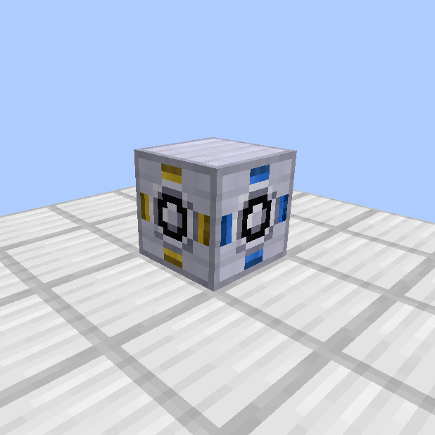
Shaft power bus is a more efficient and powerful method of uniform shaft power distribution to multiple machines from a single power source and combines functions of shaft junctions, gearboxes, bevel gears and shafts into one unit. The result significantly simplifies the splitting of power from a single power source, reducing cost in materials and space needed for such setups.
The power is distributed equally among all the shaft power bus units connected to a machine although torque and speed of each individual shaft power bus can be adjusted proportionally, akin to placing a gearbox between a shaft junction and the machine.
Rotarycraft Handbook Description[]
"The power bus pieces actually distribute the power depending on their selected options. Each side has a corresponding item slot; put a shaft or gear unit there to control the outputted speed and torque. Invalid or missing items cause the side to be ignored. Use the adjecent buttons to control the torque(τ)/speed(ω) options."
Interface[]
Shaft Power Bus Controller needs to be placed down first. From it, a series of shaft power buses can be chained in order, like a pipe. Units should not be placed randomly, skipping the chain, else the power connection to the controller may not be established properly.
The direction in which shaft power buses are chained can change and snake around, as long as each unit is connected to the previous one through a side.
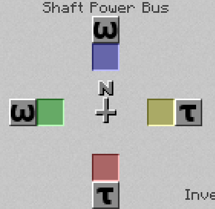
Each shaft power bus has 4 active sides that can function as inputs (from another bus or the controller) or outputs (to other buses or to machines). The side facing the adjacent shaft power bus or the shaft power bus controller, disappears from the interface of that shaft power bus, as it cannot be used to output power to a machine. Remaining outputs are color coded to the visible sides of the shaft power bus. Colors are oriented in the world relative to the compass shown on the interface and are always in the same direction.
Once output direction is decided, a shaft unit must be placed into the corresponding color square in the interface in order to route output to that side. If you wish to change torque or speed of that particular output, instead of the shaft unit you can put in 2x, 4x, 8x and 16x gears (NOT gearboxes), and switch the ratio in favor of speed or torque by pressing on the letter next to the color box and changing it from 𝜏 (torque) to ω (speed), the way you would by shift right clicking the gearbox. Note that the power output per shaft power bus will remain the same, only the speed and torque can be changed, same as it would be if you were using a gearbox.
If a color box is left empty, the side will be ignored and no power will be outputted. If no color boxes are used, the power will be passed through from preceeding bus to the following bus, without loss, thus making that bus unit into a shaft.
Note that although shaft power bus has the ability to function as a shaft or a bevel gear, it cannot be replaced by either of those units in the shaft power bus chain. Similarly, in a setup with shafts and bevel gears, lone shaft power bus will do nothing.
Angular Transducer Output[]
- Coordinates of the power source connected to the controller
Tips & Tricks[]
- In order to monitor output on each side, dynamometer or a machine with angular transducer should be used, as power output per side is not reported on the shaft power bus itself.